
Views: 137 Author: Site Editor Publish Time: 2026-08-24 Origin: Site


Discharge delays, product degradation, and pipeline blockages at the destination facility directly erode profit margins and incur severe demurrage charges. Uncontrolled pneumatic discharge in a bulk ISO tank container leads to severe operational failures. These failures include pipeline blockages, cargo compaction ("rat-holing"), product shearing, electrostatic hazards, and catastrophic vessel over-pressurization. Operators must manage airflow precisely to maintain product integrity and ensure safe unloading operations.
Optimizing discharge requires a precise technical evaluation of pressure regulation, valve configurations, fluidization systems, and air supply metrics. You must evaluate these factors before procuring or leasing an intermodal tank container. Understanding the mechanics of pneumatic flow control ensures consistent mass flow rates. It prevents material bridging and protects both the cargo and the equipment from damage on the site.
Pneumatic flow control relies on balancing internal vessel pressure (top air) with conveying line pressure (booster air); improper ratios cause material bridging or pipeline plugging.
Selecting the correct fluidization system (aeration pads vs. cones) within the tank container is dictated entirely by the cargo’s bulk density, particle size distribution, and hygroscopic properties.
Standard horizontal 20ft ISO tank container configurations require careful management of multi-hopper discharge setups or specialized tipping chassis to match the efficiency of vertical silo tanks.
Safety and compliance (ASME, ADR, and EN standards) mandate rigorous maintenance of pressure relief valves (PRVs), vacuum safety valves, and continuous grounding/earthing to mitigate electrostatic risks during high-velocity product flow.
Pneumatic conveying physics dictates the success of any bulk discharge operation. The system must achieve a steady mass flow rate. It must guarantee zero product degradation and leave minimal residual cargo (heel). Safe operating limits must govern the entire process. Dense phase conveying moves material in slugs using high pressure and low velocity. Dilute phase conveying suspends particles in a high-velocity air stream using lower pressure. Knowing which phase applies to your cargo dictates how you set up the manifold.
When you stand next to a discharging unit, you can hear the difference between a smooth flow and a struggling system. A struggling system surges, the hoses kick violently, and the compressor labors. A smooth system maintains a steady hum, indicating the air-to-product ratio is dialed in correctly. Achieving this requires understanding the interplay between top air and fluidization air.
Top-air pressure pushes the cargo downward toward the discharge outlet. Fluidization air aerates the cargo. Booster air drives the aerated material forward through the discharge line. Balancing these airflows is critical for continuous movement. If you push too hard from the top without enough booster air, you pack the discharge cone solid. If you use too much booster air without enough top pressure, you blow clean air into the silo while the cargo sits in the tank.
Operators must calculate the optimal pressure differential based on conveying distance, line diameter, and receiving silo height. This differential typically ranges from 1.5 to 2.0 bar (21.7 to 29 PSI). Air volume requirements (CFM or m³/min) determine the system's ability to maintain velocity above the saltation limit. Falling below this limit causes product settling and immediate pipeline blockages.
Determine the bulk density of the cargo to establish baseline air volume requirements.
Measure the total conveying distance, including vertical lifts to the receiving silo.
Calculate the expected pressure drop across the pipeline diameter (usually 3-inch or 4-inch).
Set the top air regulator to maintain the required pushing force without exceeding the vessel's maximum allowable working pressure (MAWP).
Adjust the booster valve to maintain line velocity above the saltation point.
Introducing compressed air alters the angle of repose of dry bulk materials. Solid particulates begin to behave like a fluid. This fluidization enables gravity to feed the material smoothly into the discharge manifold. Proper aeration prevents material from interlocking and halting the flow. You are essentially lubricating the dry particles with air.
Over-aeration poses significant risks. It causes channelling, where air bypasses the material entirely, shooting straight up through the cargo and out the top. Under-aeration leads to compaction, bridging, and core flow, where only the material directly above the outlet discharges, leaving a solid ring of cargo stuck to the walls. Operators must adjust air pressure dynamically to match the specific characteristics of the dry bulk cargo.
Flow control mechanics vary significantly based on the chassis design. A tipping 20ft ISO tank container uses gravity to slide material toward a single rear discharge cone. This design simplifies fluidization requirements and accelerates unloading times. The operator elevates the tank, and gravity does half the work, requiring less aggressive aeration to keep the material moving.
Multi-hopper horizontal designs require sequential discharge of individual hoppers. Operators must manage top air and fluidization air for each hopper independently. This non-tipping configuration demands higher operator skill to prevent pressure drops and material cross-contamination between hoppers. You have to empty them in a specific sequence, usually rear to front, to keep the discharge line clear and maintain consistent line pressure.
Specific mechanical and pneumatic hardware regulates flow within the system. Understanding these components helps operators troubleshoot blockages and optimize unloading speeds. Every valve and manifold plays a distinct role in maintaining the correct air-to-product ratio. You cannot manage what you do not understand, and knowing the hardware is the first step to mastering the discharge process.
Proportional control valves manage the volume of air entering the ullage space. These valves allow operators to fine-tune internal pressure. Non-return check valves prevent product backflow into the air supply lines. This protection is vital for maintaining compressor integrity. If a check valve fails, dust blows back into the compressor, destroying the rotors in minutes.
The booster valve injects auxiliary air directly into the discharge pipeline. This line-air assists flow and clears restrictions before they become solid plugs. Operators use the booster valve to adjust the conveying velocity independently of the internal tank pressure. It acts as the accelerator pedal for the discharge line.
Bottom discharge valves throttle the flow of fluidized material into the pipeline. Butterfly valves offer a standard, cost-effective solution. However, they are prone to wear when handling abrasive cargo. Pinch valves and specialized ball segment valves provide precise flow throttling and superior wear resistance.
Discharge cone design and manifold geometry directly affect frictional pressure drop. Standard pipe sizing typically utilizes 3-inch or 4-inch diameters. Smooth transitions within the manifold reduce turbulence and prevent particle degradation during high-velocity discharge. Sharp bends or mismatched pipe diameters create turbulence zones that degrade fragile cargo and accelerate wear on abrasive loads.
Valve Type | Primary Application | Advantages | Disadvantages |
|---|---|---|---|
Standard Butterfly | General dry bulk, non-abrasive | Cost-effective, easy to replace | Prone to rapid wear with abrasives |
Pinch Valve | Abrasive powders, fragile granules | Excellent throttling, no metal contact | Requires compressed air to actuate, higher cost |
Ball Segment | Cohesive powders, high-pressure systems | Precise control, cuts through material columns | Heavy, expensive to maintain |
Aeration materials must withstand temperature fluctuations, abrasion, and product clogging. Sintered stainless steel offers maximum durability for abrasive materials. Permeable canvas provides excellent air distribution for fine powders. Silicon fluidizing nozzles prevent material backflow while delivering targeted air bursts.
Porous plastics offer chemical resistance for specialized chemical powders. The choice of fluidization media dictates the maintenance schedule and the overall lifespan of the internal discharge components. If you run hot air through standard canvas pads, they will degrade and tear, blowing fabric into the customer's silo.
Dry bulk friction generates massive amounts of static electricity. Grounding lugs and electrical continuity links across pipe joints safely dissipate this charge. Continuous earthing prevents spark generation in dust-rich environments. You can literally see the static arc off ungrounded hoses in low-light conditions.
Operators must verify grounding connections before initiating any pneumatic discharge. Failure to maintain electrical continuity risks catastrophic dust explosions, especially when handling combustible powders like flour or plastic resins. A simple multimeter check across the hose connections can prevent a site disaster.
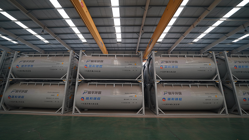
Equipment specifications must map directly to actual cargo behaviors. This alignment guides procurement and leasing decisions. Different materials require vastly different pneumatic handling strategies to ensure safe and efficient discharge. You cannot use a one-size-fits-all approach when moving from plastic pellets to cement powder.
Cargo Type | Flow Characteristics | Optimal Configuration | Key Risks |
|---|---|---|---|
Plastic Pellets | Free-Flowing | Dilute phase, low pressure, high volume | Friction melting, product shearing |
Cement / Flour | Cohesive Powder | Dense phase, high pressure, extensive aeration | Bridging, moisture caking, compaction |
Silica Sand | Highly Abrasive | Hardened components, polyurethane lining | Rapid valve wear, pipe erosion |
Free-flowing granules require high-volume, lower-pressure air. This dilute phase conveying prevents product shearing. It also stops degradation and melting caused by friction heat. Excessive pressure damages the granules and creates unwanted dust, which the receiver will reject.
Rotary feeder valves or gravity-assisted pneumatic setups limit high-velocity impact. These components gently introduce the granules into the air stream. Preserving the physical structure of the product is the primary objective during discharge. If you blast plastic pellets through a 4-inch line at maximum pressure, you will create angel hair (long strands of melted plastic) that clogs the receiver's filters.
Cohesive powders demand high-pressure fluidization. Dense phase conveying pushes these heavy materials efficiently. Extensive aeration pad coverage eliminates cohesive bridging inside the Bulk ISO Tank Container. The air must penetrate the powder mass completely to get it moving.
Integrated moisture traps, coalescing filters, and air dryers are absolute requirements in the compressor line. Hygroscopic powders absorb moisture rapidly. Wet air causes these powders to cake and harden, permanently damaging the cargo and the internal fluidization pads. If you pump humid air into a load of cement, you are essentially mixing concrete inside the vessel.
Verify the compressor's air dryer is functioning and draining properly.
Pre-pressurize the tank slowly to allow air to permeate the cohesive powder block.
Open the fluidization valves fully before cracking the bottom discharge valve.
Monitor the line pressure gauge; sudden drops indicate a rat-hole has formed.
Use pneumatic vibrators sparingly to collapse bridges without compacting the material further.
Abrasive materials destroy standard pneumatic components quickly. Operators must select hardened components to extend system lifespan. Polyurethane-lined discharge pipes resist internal scouring. Abrasion-resistant butterfly valve seats maintain their seal despite constant exposure to sharp particulates.
Frequent inspections of the discharge manifold are necessary when handling abrasives. Preventative replacement of wear parts prevents unexpected blowouts and hazardous material spills during pressurized unloading operations. A blowout on a pressurized sand line acts like a sandblaster, cutting through adjacent equipment and posing a severe hazard to site personnel.
Selecting tank specifications involves commercial and operational compromises. Logistics managers must balance payload capacity against specialized unloading capabilities. The right equipment choice depends heavily on the destination facility's infrastructure and the specific routes being run.
Standard horizontal units offer versatility and lower tare weight. They maximize payload capacity for general dry bulk transport. However, they require more complex multi-hopper management during discharge. Specialized tipping chassis or vertical silo tanks simplify unloading but add significant equipment weight, reducing the total amount of cargo you can legally haul.
Leasing multi-purpose tanks provides fleet flexibility. Highly specialized, cargo-specific units offer faster discharge times but limit backhaul opportunities. Buyers must evaluate the cost-to-benefit ratio based on their primary trade routes and cargo contracts. If you only haul cement, a specialized silo tank makes sense. If you haul cement one way and plastic pellets the other, you need a versatile horizontal unit.
Relying on facility-provided compressed air introduces variability. Air quality, pressure, and filtration standards differ between sites. Truck-mounted blowers provide consistent, controlled air supply. These PTO-driven units give the operator complete control over the discharge parameters, eliminating reliance on the receiver's potentially faulty equipment.
Air cooler installations reduce air temperature significantly. Hot compressed air damages heat-sensitive cargo like plastic resins. Aftercoolers protect the product and ensure the pneumatic discharge operates within safe thermal limits. Pumping 150-degree air into a load of low-melt resin will fuse the entire load into a solid block.
Discharge operations contain critical failure points. Engineering out these risks protects personnel and equipment. Strict adherence to safety protocols prevents catastrophic accidents during pressurized unloading. The site environment is unforgiving, and shortcuts inevitably lead to equipment damage or injury.
Pressure Relief Valves (PRVs) protect the vessel from structural failure. Rupture discs provide a secondary fail-safe against extreme over-pressurization. Mandatory testing schedules ensure these devices function correctly under stress. You must never tamper with a PRV setting in the field.
Vacuum safety valves prevent tank implosion. Rapid depressurization or vacuum-assisted loading creates severe negative pressure. Operators must never bypass safety mechanisms to speed up discharge times. Bypassing safety controls leads directly to equipment destruction and severe injury. A collapsed tank is a total loss and a massive safety incident.
Standard operating procedures dictate how to clear pipeline plugs safely. Operators use the booster line to break up blockages without depressurizing the entire system abruptly. Gradual pressure adjustments prevent the plug from compacting further. If you hammer the line with full pressure, you will turn a loose plug into a solid brick.
Acoustic cleaners or pneumatic vibrators serve as secondary flow aids. They break up stagnant product zones and prevent rat-holing. These devices maintain continuous material flow when primary fluidization proves insufficient. Use them in short bursts; leaving a vibrator running continuously on a compacted load will only pack it tighter against the tank walls.
A clogged dust collector at the receiving silo causes immediate backpressure. This backpressure slows or completely halts the discharge flow of the ISO tank container. The system cannot push material into a pressurized void. The air has to go somewhere, and if the silo can't vent, the flow stops.
Operators must verify silo filter status before commencing discharge. Vent filters must exhaust conveying air efficiently. Proper silo maintenance is just as critical as tank maintenance for successful pneumatic unloading. If the silo pressure gauge starts climbing rapidly, shut down the discharge immediately and have the site check their baghouse.
The human element remains the most critical factor. Operators must read pressure gauges accurately. They must monitor air-to-product ratios continuously. Adjusting valves incrementally maintains system stability. You don't just yank valves open; you ease them into position while watching the gauges.
Binary valve movements (fully open to fully closed) cause pressure spikes and pipeline plugs. Comprehensive training ensures operators understand the physics of pneumatic conveying. Skilled operators adapt to changing flow conditions and prevent blockages before they occur. They listen to the compressor, watch the hoses, and read the gauges simultaneously.
Audit your most frequently transported cargo's bulk density, particle size, and moisture sensitivity before finalizing specifications.
Consult with tank engineers to run flow-simulation calculations for your specific material to determine the exact fluidization requirements.
Request detailed technical drawings of the discharge manifold to confirm flow efficiency and identify potential turbulence zones.
Verify compressor compatibility with your existing fleet assets to ensure seamless integration and adequate air supply.
Establish strict standard operating procedures for your drivers, focusing on incremental valve adjustments and continuous gauge monitoring.
A: The standard operating pressure typically ranges from 1.5 to 2.0 bar (21.7 to 29 PSI). The exact pressure depends on the conveying distance, pipeline diameter, and the specific bulk density of the cargo being discharged.
A: You prevent moisture contamination by installing integrated moisture traps, coalescing filters, and air dryers in the compressor line. This equipment removes water vapor from the compressed air before it enters the tank, protecting hygroscopic cargoes from caking.
A: Dense phase conveying uses high pressure and low velocity to push heavy, cohesive materials in slugs. Dilute phase conveying uses low pressure and high velocity to suspend free-flowing granules in the air stream, preventing product degradation.
A: Product bridging occurs due to improper air-to-product ratios, under-aeration, or moisture ingress. Adjusting the fluidization air pressure and ensuring the aeration pads are clean and functioning usually resolves bridging issues.
A: No. Liquid tanks lack the necessary fluidization pads, specialized discharge cones, and top-air manifolds required to aerate and convey dry bulk solids pneumatically.
A: Pressure relief valves must undergo rigorous inspection and calibration at least every 2.5 years during the mandatory statutory testing, though visual inspections should occur before every loading and discharge operation.
A: The booster line injects auxiliary compressed air directly into the discharge pipeline downstream of the bottom valve. This air breaks up material plugs and maintains conveying velocity without requiring sudden depressurization of the main vessel.


