
Views: 123 Author: Site Editor Publish Time: 2026-08-28 Origin: Site


Frame misalignment acts as a silent drain on fleet profitability, directly causing accelerated tire wear, increased aerodynamic drag, and elevated fuel consumption. Unlike enclosed dry vans, a skeleton trailer relies entirely on its bare chassis rails for structural integrity. Without a rigid deck to mask or resist twisting forces, identifying and verifying true frame alignment requires specialized diagnostic approaches that go far beyond standard visual inspections. Moving from reactive tire replacement to proactive alignment verification requires a deep understanding of exact measurement protocols, acceptable engineering tolerances, and the specific diagnostic equipment necessary to ensure true tracking down the highway. Fleet managers must treat the chassis not just as a carrier, but as a precision-aligned platform where even minor deviations compound into massive operational losses over thousands of miles.
Precision is Non-Negotiable: Acceptable thrust angle tolerances for a skeleton trailer are typically within fractions of an inch; exceeding these limits drastically increases rolling resistance.
Methodology Matters: While tram gauges offer baseline diagnostics, modern fleets require computerized laser alignment systems for verifiable, repeatable accuracy.
Structural Context: Alignment protocols must account for the specific flex and load-bearing characteristics of container-carrying chassis, which differ significantly from standard flatbed designs.
Industry Standards Compliance: Adhering to Technology & Maintenance Council (TMC) Recommended Practices (e.g., TMC RP 708A and RP 712) ensures legal compliance, road safety, and optimal component longevity.
Operational Impact: Routine alignment verification directly lowers fleet expenses by extending tire life by up to 30% and improving fuel efficiency by 1-2%.
The foundation of trailer alignment relies on establishing an accurate thrust line. This imaginary line extends from the center of the rear axle group directly through the exact center of the kingpin. When the thrust line aligns perfectly with the geometric centerline, the vehicle tracks straight without crabbing or dog-tracking. Baseline engineering tolerances for axle tracking and frame squareness dictate that deviations must remain minimal. Axle misalignment occurs when the wheels do not point straight ahead relative to the chassis, whereas frame deformation involves the actual steel I-beams bending, twisting, or diamonding under stress.
According to TMC RP 708A specifications, the maximum allowable tracking error is typically ±1/8 inch or 3.1mm. Exceeding this tight tolerance leads to significant rolling resistance. Mechanics must measure the distance from the kingpin to the axle ends to verify this. If the left side measures 400 inches and the right side measures 400.5 inches, the axle is out of square, and the tires will drag sideways. Perfect tracking means the trailer follows the exact path of the tractor, minimizing the scrub radius and ensuring all tires roll freely rather than fighting the pavement.
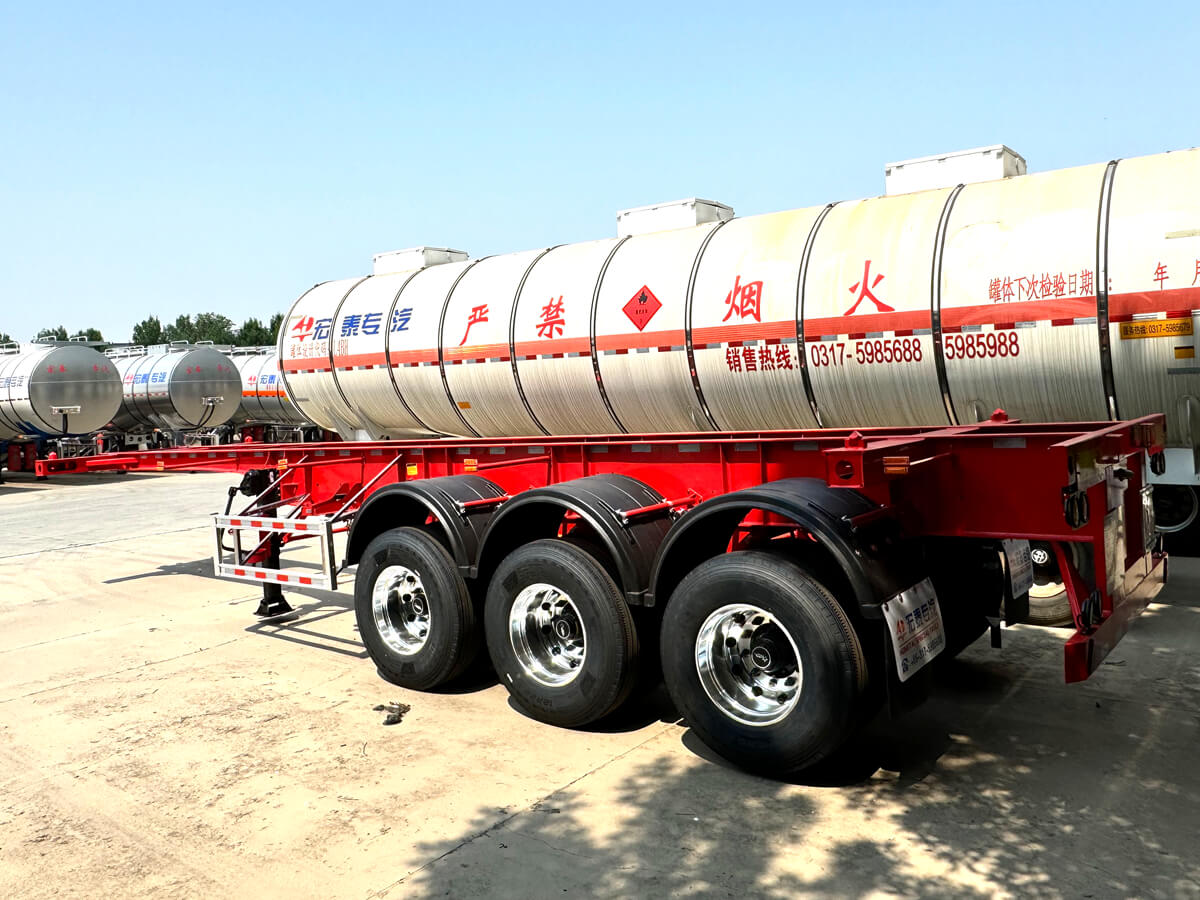
The absence of a solid floor or deck significantly impacts frame rigidity during measurement. A semi trailer designed as a bare chassis exhibits entirely different torsional rigidity compared to the stiffer, reinforced structure of a platform semi trailer or a standard flatbed trailer. Flatbeds utilize crossmembers and a solid deck that lock the main rails in place, resisting diagonal twisting. A bare chassis lacks this upper reinforcement.
The localized stress points of twist locks on a container trailer necessitate specific measurement reference points to ensure accuracy. When a heavy shipping container drops onto the bolsters, the dynamic flexing alters static alignment readings. The frame naturally bows and twists depending on load distribution. Therefore, measurement must occur on a dead-level surface. If the shop floor has a slope or uneven concrete slabs, gravity will twist the bare rails, skewing the diagnostic data and leading mechanics to make incorrect suspension adjustments.
The kingpin-to-bolster dimension must be verified first to rule out chassis frame twist. This initial check establishes the structural baseline before anyone touches a suspension bolt. The geometry of the "Golden Triangle" is the standard here. Mechanics measure diagonally from the kingpin center to the rear-most left and right ISO container twist locks. These twist locks are fixed points welded directly to the bolsters.
If the bolsters are misaligned or the frame is diamonded, this error propagates down to the suspension hangers. Such structural faults cause permanent dog-tracking. You can perfectly align the axles relative to the suspension hangers, but if the hangers are welded to a twisted frame, the trailer will still crab down the highway. Verifying the Golden Triangle ensures the foundation is square before attempting to true the axles.
Computerized laser alignment systems represent the industry standard for precision diagnostics in modern heavy-duty shops. The process involves mounting laser targets directly to the kingpin and the axle hubs. Specialized software then calculates the exact thrust angle, scrub radius, and camber or caster if applicable. The lasers shoot a beam from the axle targets to the kingpin target, instantly calculating the geometric relationship down to the millimeter.
A major benefit of this method is the ability to generate verifiable, timestamped digital reports for fleet maintenance records. These reports prove that the equipment was maintained to spec. Laser systems easily calibrate for multi-axle configurations, including tandem, tri-axle, and spread-axle designs. The software guides the technician through the adjustment process, showing real-time changes on a monitor as they turn the suspension adjustment rods or shift the axle blocks.
Optical and 3D camera-based measurement systems use high-definition sensors to map the chassis in three dimensions. These systems excel at detecting micro-deformations in the main I-beams that traditional methods might miss. Instead of relying solely on hub-mounted targets, optical systems can scan the entire side profile of the chassis.
Photogrammetry plays a significant role in this process, capturing the entire structural geometry of the trailer in under 10 minutes. This rapid data acquisition allows for quick turnaround times in busy maintenance facilities. Drive-through optical scanners can evaluate a chassis as it rolls through the inspection bay, instantly flagging units that require suspension adjustments or frame straightening without requiring a technician to manually set up targets.
The legacy process of mechanical measurement involves running strings or measuring diagonally from the kingpin to the axle ends. Standard-length spring-loaded tram bars serve as practical tools in field-triage environments. A technician places the kingpin adapter on the pin and extends the tram bar to the center hole of the axle spindle on both sides.
However, mechanical methods have notable limitations. Human error, tape sag, and a lack of repeatability plague manual measurements. If the technician holds the tape measure at a slight angle, or if the tape sags in the middle over a 40-foot span, the reading will be off by a quarter-inch or more. Tram gauges function best as a viable field-triage tool to identify gross misalignment rather than a definitive verification protocol for precision adjustments.
Alignment Method | Accuracy Level | Setup Time | Best Use Case |
|---|---|---|---|
Tram Gauge / Tape Measure | Low to Moderate (± 1/4 inch) | 15-20 Minutes | Field triage, emergency roadside checks, gross misalignment identification. |
Computerized Laser System | High (± 1/32 inch) | 30-45 Minutes | Standard shop alignments, routine preventative maintenance, compliance reporting. |
3D Optical Scanning | Very High (± 1/64 inch) | Under 10 Minutes | High-volume fleet inspections, detecting frame diamonding, rapid throughput bays. |
Comparing the upfront capital expenditure of laser systems against the labor costs of manual verification is essential for fleet managers. While laser systems require a significant initial investment, they drastically reduce measurement time and improve accuracy. Manual tram gauge alignments take longer and often require rework if the technician misreads the tape.
A break-even analysis based on fleet size and average annual tire expenditure often reveals that the long-term savings in tire wear and fuel efficiency justify the cost of advanced diagnostic equipment. For a fleet running hundreds of chassis, saving just one set of dual tires per trailer annually pays for a top-tier laser alignment rack within the first year of operation.
Throughput speed is a critical factor for high-volume fleets operating out of busy ports or rail yards. Drive-through optical alignment scanners offer faster processing compared to bay-bound laser setups. The chosen verification method must integrate smoothly into standard preventative maintenance schedules to avoid excessive downtime.
Fleet managers must analyze the trade-offs of developing in-house diagnostic capabilities versus outsourcing alignment verification to specialized heavy-duty alignment shops. Outsourcing makes sense for small operations, but large fleets lose too much time shuttling equipment back and forth to third-party vendors. Bringing laser or optical systems in-house allows mechanics to verify alignment during standard DOT inspections.
DOT and CVSA out-of-service criteria strictly regulate suspension tracking, axle alignment, and frame integrity. Inspectors look for signs of severe dog-tracking or tires rubbing against the frame rails. Non-compliance results in severe penalties, vehicle grounding, and delayed freight.
Documented alignment verification serves as vital liability protection in the event of a tracking-related collision. If a chassis swings into another lane due to severe misalignment and causes an accident, maintenance records will be subpoenaed. Maintaining accurate digital records from a laser alignment system demonstrates a commitment to safety and proactive maintenance, mitigating legal risks associated with equipment failure.
The cost of dog-tracking is substantial. A 1/4-inch misalignment translates to dragging a tire sideways for miles over a year, drastically reducing its lifespan. Tires are one of the highest operating expenses for any fleet. When axles are not parallel, the tires fight each other, scrubbing rubber off the tread with every revolution.
Specific tire wear signatures directly indicate misalignment types. Cupping, feathering, and inner or outer shoulder wear tell a mechanic exactly what is wrong with the suspension geometry. Verified alignment correlates with specific reductions in rolling resistance. Less rolling resistance means the tractor does not have to work as hard to pull the load, leading to measurable fuel savings and significantly lower operational costs over the trailer's lifecycle.
Feathering: Indicates excessive toe-in or toe-out on the axle.
One-Sided Shoulder Wear: Points to camber issues or a bent axle housing.
Diagonal Wear: Often caused by loose wheel bearings combined with tracking errors.
Cupping: Usually related to worn shock absorbers, but exacerbated by misalignment.
Verified alignment prevents premature wear on critical components, including bushings, equalizers, shock absorbers, and wheel bearings. When a chassis tracks straight, the suspension components articulate vertically as designed. When misaligned, lateral crabbing forces introduce side-loading stress that tears apart rubber bushings and grinds down metal equalizers.
By eliminating these lateral forces, the structural welds of the bare chassis are preserved over the long term. Constant side-loading causes fatigue cracking around the suspension hangers and crossmember gussets. Reducing mechanical stress extends the service life of the entire suspension system and prevents catastrophic failures on the road.
Relying on out-of-calibration laser or optical sensors yields false positive alignments, leading mechanics to make improper adjustments. If the laser head is dropped or bumped, the internal sensors can shift. To mitigate this risk, facilities must establish strict, vendor-mandated calibration schedules.
Shops must utilize baseline calibration jigs regularly to verify the equipment before attaching it to a vehicle. Consistent equipment maintenance ensures diagnostic accuracy. A bad alignment performed with uncalibrated equipment is worse than no alignment at all, as it actively ruins the suspension geometry.
Technicians applying passenger vehicle or rigid-truck alignment logic to articulated chassis often make critical errors. A bare chassis behaves differently than a rigid box truck. Mitigation requires investing in specialized heavy-duty alignment training.
This training must focus heavily on kingpin-to-axle geometry, suspension equalization, and the nuances of sliding tandems. Mechanics need to understand how to square the front axle to the kingpin first, and then parallel the rear axle to the front axle. Skipping steps or measuring from the wrong reference points ruins the entire process.
Performing an alignment on a trailer with worn-out kingpins, loose wheel bearings, or failed suspension bushings renders the alignment useless. As soon as the vehicle hits the road, the loose components shift, and the alignment is lost. Facilities must mandate a pre-alignment mechanical inspection checklist.
Inspect the kingpin for wear using a go/no-go gauge.
Check wheel bearing end-play with a dial indicator.
Pry against the suspension hangers to check for worn torque arm bushings.
Inspect the equalizer for excessive wear or seized bolts.
Verify all U-bolts are torqued to factory specifications.
Attempting to align axles on a chassis that has a permanently diamond-shaped or twisted frame is ineffective. You cannot fix a bent frame with suspension adjustments. A comprehensive frame squareness verification, measuring diagonal dimensions of the main I-beams, must be mandated before any axle adjustments are made.
Severely deformed chassis require the use of heavy-duty frame-straightening racks prior to alignment. Mechanics must chain the frame down and use hydraulic rams to push or pull the I-beams back into square. Only after the foundation is verified straight can the axle alignment process begin.
Audit current tire wear patterns across the chassis fleet to identify immediate alignment needs and prioritize shop scheduling.
Evaluate the return on investment of implementing in-house laser alignment systems versus outsourcing to specialized facilities based on your specific fleet size.
Establish a strict mileage-based alignment verification interval integrated directly into routine preventative maintenance schedules.
Mandate a comprehensive suspension component inspection checklist before any technician connects alignment equipment to a chassis.
A: Alignment verification is recommended every 80,000 to 100,000 miles. It should also be performed immediately following a collision, a severe pothole strike, or upon detecting uneven tire wear patterns during routine yard checks.
A: Industry standards, including TMC RP 708A guidelines, generally dictate that measurements should not deviate by more than 1/8 to 1/4 inch, depending on specific manufacturer specifications and the type of suspension installed.
A: No, axles cannot be properly aligned if the foundational frame is compromised. The frame must first be squared and repaired on a heavy-duty frame rack before axle alignment is attempted.
A: Without a solid deck, the bare chassis is more susceptible to twisting under load. This requires precise measurement points directly on the main rails, bolsters, and twist locks to ensure accurate alignment.
A: Primary symptoms include diagonal or rapid shoulder tire wear, visible dog-tracking in the driver's mirrors, and driver complaints regarding handling issues or the vehicle pulling heavily to one side.
A: Small fleets often benefit more from outsourcing to specialized heavy-duty shops. However, fleets with over 50 assets can typically recoup the investment on in-house equipment quickly through substantial tire savings.
A: Yes, component deflection under load can cause inconsistent tracking readings. This emphasizes the critical need for a thorough mechanical inspection of all suspension parts prior to performing alignment verification.


